
Logical and physical design relates to the two ways Data Flow Diagrams (DFD) represent systems. A logical DFD indicates just what a system does, a physical DFD indicates how a system does it.
In the design stage typically a logical DFD is created before a physical DFD, as the what of the data, processes and data stores should be created first before how they should be implemented.
Below is an example of the difference between a logical and physical DFD
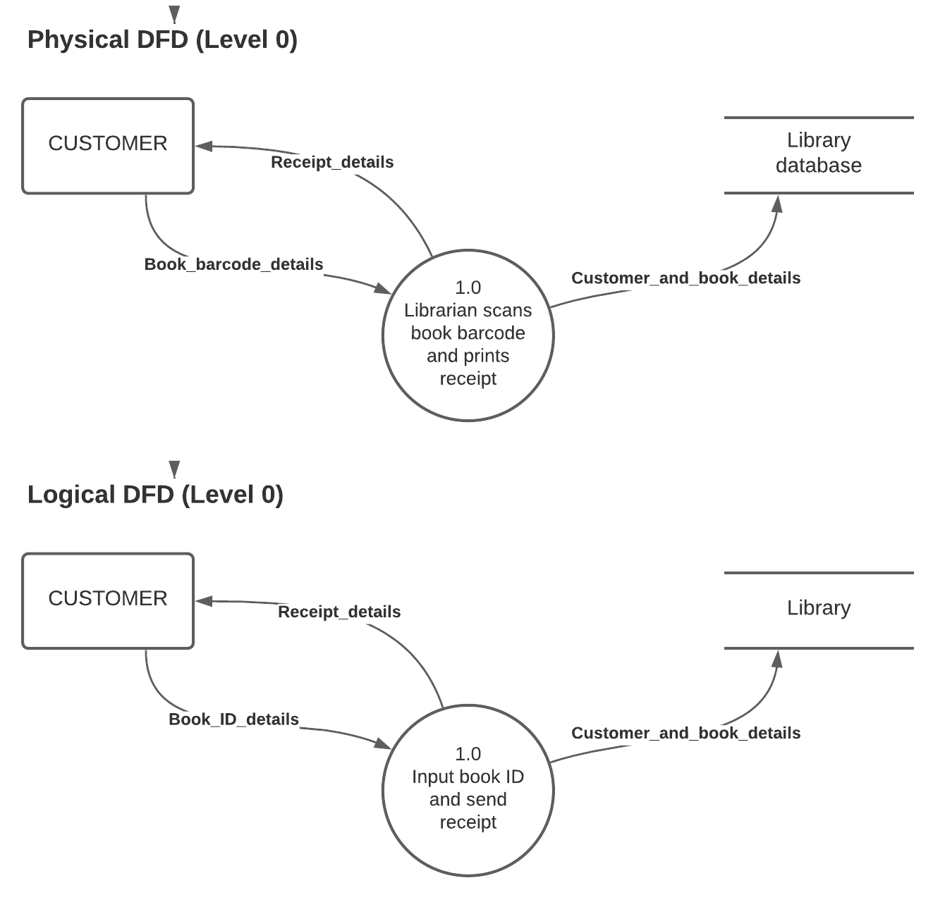
Note the process in the physical DFD identifies things like personnel, specific technologies (barcode) and paper, whereas the logical DFD does not identify how anything is physically done.
It’s important to note the difference between a logical and physical DFD does not mean the rule that no physical item can be in flows of data, they are still flows of data and are just “details”. A cash payment can never become “cash payment” as a data flow, it would always be the flow of the payment details.
Typically logical and phyisical DFDs are discussed in the Design stage of the SDLC, however, during the Analysis stage of the SDLC a DFD may be used to help analyse an existing system. At that time typically you are not interested in how an existing system is implemented as you are to redesign it, therefore you are only interested in the flows of data and what happens to those flows of data within the processes and datastores.